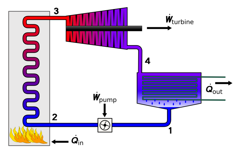
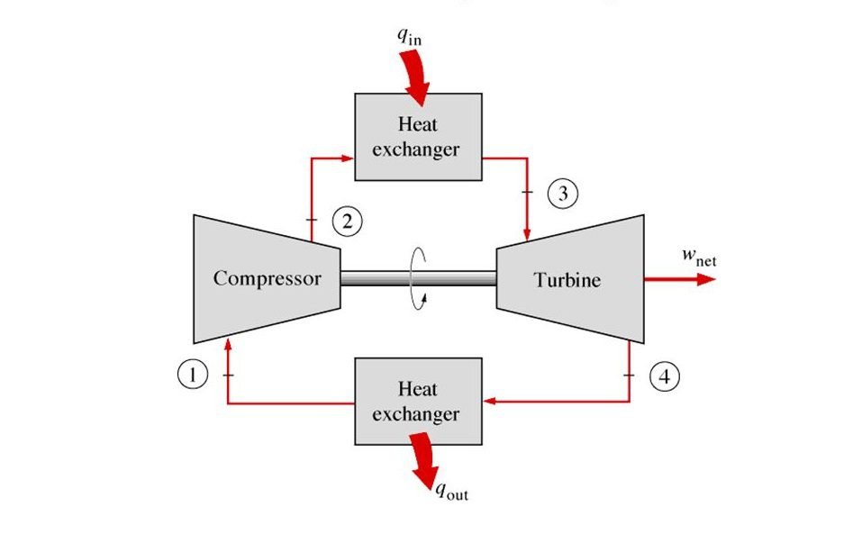
Brayton cycle is a gas power cycle by Geroge Brayton in 1870. The Brayton cycle consists of a compressor, heat exchanger, turbine, and another heat exchanger.
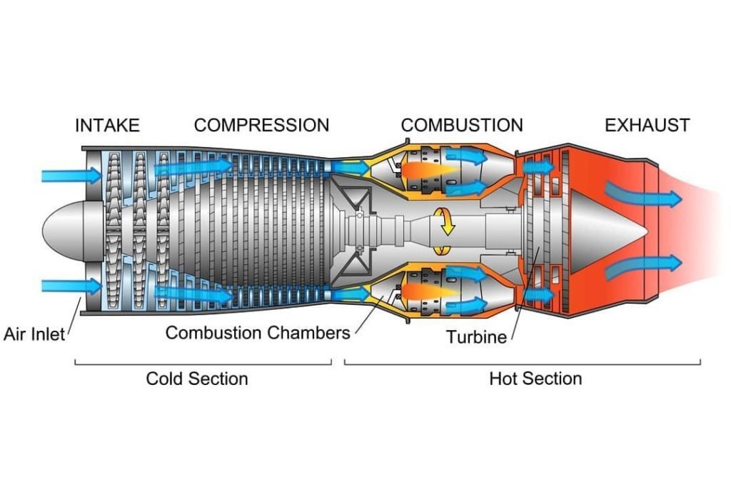
Now you may want to ask, where do we use this cycle in our real world? And that’s a very good question. The common applications for this cycle are gas power plants and aircraft. Now let’s talk about the theoretical concept of the Brayton cycle with a reference to a jet engine to make it easier for us to understand.
But before we start the discussion, we want to note first that in dealing with the Brayton cycle we assume that our working fluid is air modeled as an ideal gas. But that is not the case for jet engines as an ideal gas in the real world does not exist. However, Jet engines use real-world air which is being treated as an ideal gas and follows the principle of the Brayton cycle.
Components of Brayton Cycle
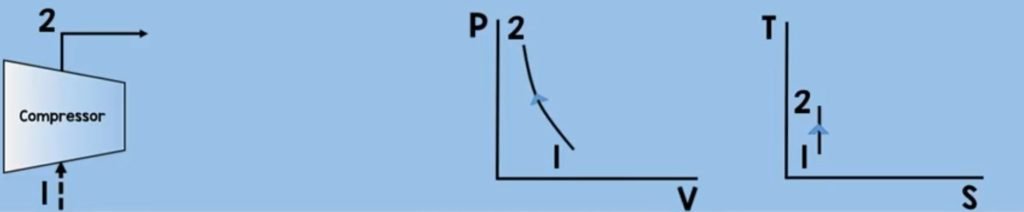
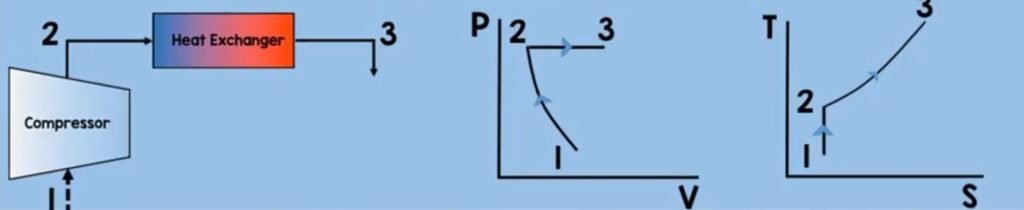
Compressor
Air will enter the compressor. Through compression (or we say decreasing the volume ) the air molecules get squeezed, increasing their pressure and temperature. In this process, we need to increase the pressure and temperature to sustain combustion while assuming that there is no change in entropy.
Now you may want to ask how to solve the work of the compressor here? we can get the work by using the control volume energy rate balance equation.
dEcv/dt = Qcv – Wcv + ΔH + ΔKE + ΔPE
Where the time rate of change of the energy contained within the control volume at time t is equal to the net rate at which energy is being transferred by heat transfer at time t minus the net rate at which energy is being transferred by work at time t plus the change in enthalpy plus the change in kinetic energy plus the change in potential energy.
Now for a control volume like this at a steady state, there will be no mass accumulation within the control volume and the time rate of change of the energy contained within the control volume at time t is zero.
Σi mi (inlet) = Σe me (outlet)
dEcv/dt = 0
Our equation now becomes
0 = Qcv – Wcv + ΔH + ΔKE + ΔPE
In addition, don’t forget that in this cycle we neglect the effects of potential energy and kinetic energy. We also assumed here that there is no undesired heat transfer to the surrounding. So now, our equation transforms into
0 = 0 – Wcv + ΔH + 0 + 0
Wcv = ΔH = m (hi – ho)
But this is not yet the final equation. In this process, we are the ones compressing the air molecules through our turbine which is attached to the same shaft of our compressor. So when the turbine rotates, the compressor rotates. In this process, our work is a work input so let’s put a negative sign on the work.
– [Wcv = ΔH = m (hi – ho)]
Let’s multiply the whole equation by negative so it can give us this final equation
Winput = m (ho – hi) = m (h2 – h1)
Heat Exchanger
Now let’s move on to the next component of Brayton cycle which is the heat exchanger or the combustion chamber of the Brayton cycle. Fuel will be injected which will mix with the pressurized air molecules. With the help of an ignitor, combustion will take place. This will further heat up the molecules thereby increasing their temperature and increasing their enthalpy. In this process, we assumed that the pressure is constant.
Now to solve for the heat addition of a control volume heat exchanger at steady-state. we just use some of the equations and assumptions that we have used on the compressor.
dEcv/dt = Qcv – Wcv + ΔH + ΔKE + ΔPE
There will be no mass accumulation within the control volume and the time rate of change of the energy contained within the control volume at time t is zero. We also neglect the effects of potential energy and kinetic energy. Importantly, we need to remember that here, the only work is the flow work and so this equation will now become
0 = Qcv – Wcv + ΔH + 0 + 0
Qcv = ΔH = m (hi – ho)
But this is not our final equation yet. Since we are providing or adding heat so now let’s put the negative sign to our heat added and then multiply the whole equation by negative
– [Qcv = ΔH = m (hi – ho)]
So that it will give us this final equation and more convenient to look at the equation.
Qadded = m (ho – hi) = m (h3 – h2)
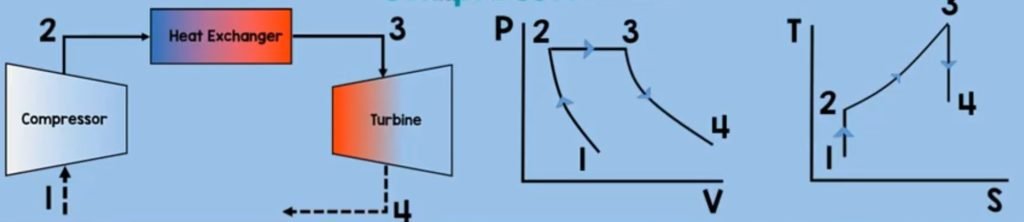
Turbine
The next component is turbine. After the heat exchanger, our heated aand energized air fuel mixture will enter and rotate the turbine. This turbine will rotate the compressor as they are in one same shaft. The air fuel mixture will also exit the turbine in a high velocity which will provide thrust to the aircraft. And as you might noticed this is an application of Newton’s third law of motion which states that for every action there is an equal and oposite reaction. In this process, just like what did in compressor a steady state control volume turbine, will have no mass accummulation (Qcv) within the control volume and the time rate of change of the energy (dEcv/dt) contained within the control volume at time t is zero.
dEcv/dt = Qcv – Wcv + ΔH + ΔKE + ΔPE
Entropy (S) is constant. There is no heat transfer to surroundings, potential and kinetic energy effects are neglected.
0 = Qcv – Wcv + ΔH + 0 + 0
But in contrast with compressor turbine expands the gas which increases its volume and decreases its pressure.
In addition, turbine generates work, so our work here is a positive. Our final equation for the work output will look like this
Woutput = m (hi – ho) = m (h3 – h4)
Heat Exchanger
Finally for the last component of Brayton cycle is the second heat exchanger. On this component, the working fluid is being exposed to the ambient air. By the second law of thermodynamics, this working fluid will transfer its heat to the surroundings.
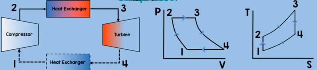
As it has higher energy value than on the air molecules on the surroundings and so this means that the heat is rejected here. Now to solve for the heat rejection we just assume that the things we have assumed on combustion chamber. Except for the fact that, our heat is positive. So our heat rejetion is
Qout = m (h4 – h1)
We really tried this to be as easy and as informative as possible.


Leave a Reply